
Modeling Injection Facilities
This document describes the physical model of injection facilities used in V5. In that model, injection facilities are connected to a manifold of injection wells where the facility tries to inject its incoming fluid. Additionally, the model supports downstream rerouting of any exceeding fluid that is not sent into the wells. Optionally, injection facilities can receive fluid from some external supply that complements the amount of fluid they receive from the production upstream.
The Physical Model
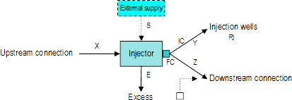
The diagram for the physical model of an injection facility has several components as depicted below:

As shown in the diagram, the injector receives fluid from some upstream connection. Optionally, it can have some external source supplying additional fluid. An injection facility has also an out connector that splits the fluid into two branches. One of these branches injects the fluid into the injection wells. The other one sends downstream whatever is left after injection.
Injection Capacity
As with any other kind of facility, injectors have a capacity that controls the total amount that they can process. That capacity is depicted in the picture above in the small square labeled FC (which stands for Facility Capacity).
Moreover, the injection branch of the split can have an injection capacity. That is shown in the diagram with the label IC. This capacity represents the amount of fluid the facility is able to inject into the wells. Instead of defining a new concept, our physical model uses the capacity of the first branch of the split to represent that capacity. Its real counterpart, however, could be assimilated to the capacity of the facility's injection pump.
Routing through an Injection Facility
An injection facility tries to inject the amount of fluid required by the injection wells. Several quantities are considered to compute the routing as illustrated below:
The required injection RI can only be honored if the following conditions hold:
- The injection capacity IC is greater or equal than the required injection RI.
- The facility capacity FC is greater or equal than RI. If FC is not defined, then this condition is ignored (i.e., FC = ∞).
- The amount of fluid X is greater or equal than RI, or there is an external supply such that X + S ≥ RI.
If these conditions do not hold, then a lower amount is injected into the wells. In general the resulting injection is the minimum min(X + S, RI, IC, FC). Note that S = 0 if there is no external supply. If there is an external supply, it is only used if the amount X is less than min(RI, IC, FC).
The second branch has the same behavior it would have in any other split: it reroutes downstream the fraction of X, if any, that is not injected. That is Z = max(0, X - min(RI, IC, FC)).
Excess
As in any other split, the calculation of the excess at an injection facility has two components. The local excess EL is present only if the facility capacity FC is defined. In that case the local excess is computed as usual: EL = max(0, X - FC). Note that if FC is not defined then it is considered infinite and the local excess is zero.
Additionally to the local excess, the non-local excess, if any, comes from the excess in the downstream connection. Since the downstream connection can receive fluid from other sources the calculation of the downstream excess follows the general rules for that kind of connections.